+++ DISCLAIMER +++
Nothing you see here is real, even though the conversion or the presented background story might be based on authentic facts. BEWARE!
Some background:
The English Electric Skyspark was a British fighter aircraft that served as an interceptor during the 1960s, the 1970s and into the late 1980s. It remains the only UK-designed-and-built fighter capable of Mach 2. The Skyspark was designed, developed, and manufactured by English Electric, which was later merged into the newly-formed British Aircraft Corporation. Later the type was marketed as the BAC Skyspark.
The specification for the aircraft followed the cancellation of the Air Ministry's 1942 E.24/43 supersonic research aircraft specification which had resulted in the Miles M.52 program. W.E.W. "Teddy" Petter, formerly chief designer at Westland Aircraft, was a keen early proponent of Britain's need to develop a supersonic fighter aircraft. In 1947, Petter approached the Ministry of Supply (MoS) with his proposal, and in response Specification ER.103 was issued for a single research aircraft, which was to be capable of flight at Mach 1.5 (1,593 km/h) and 50,000 ft (15,000 m).
Petter initiated a design proposal with F W "Freddie" Page leading the design and Ray Creasey responsible for the aerodynamics. As it was designed for Mach 1.5, it had a 40° swept wing to keep the leading edge clear of the Mach cone. To mount enough power into the airframe, two engines were installed, in an unusual, stacked layout and with a high tailplane This proposal was submitted in November 1948, and in January 1949 the project was designated P.1 by English Electric. On 29 March 1949 MoS granted approval to start the detailed design, develop wind tunnel models and build a full-size mock-up.
The design that had developed during 1948 evolved further during 1949 to further improve performance. To achieve Mach 2 the wing sweep was increased to 60° with the ailerons moved to the wingtips. In late 1949, low-speed wind tunnel tests showed that a vortex was generated by the wing which caused a large downwash on the initial high tailplane; this issue was solved by lowering the tail below the wing. Following the resignation of Petter, Page took over as design team leader for the P.1. In 1949, the Ministry of Supply had issued Specification F23/49, which expanded upon the scope of ER103 to include fighter-level manoeuvring. On 1 April 1950, English Electric received a contract for two flying airframes, as well as one static airframe, designated P.1.
The Royal Aircraft Establishment disagreed with Petter's choice of sweep angle (60 degrees) and the stacked engine layout, as well as the low tailplane position, was considered to be dangerous, too. To assess the effects of wing sweep and tailplane position on the stability and control of Petter's design Short Brothers were issued a contract, by the Ministry of Supply, to produce the Short SB.5 in mid-1950. This was a low-speed research aircraft that could test sweep angles from 50 to 69 degrees and tailplane positions high or low. Testing with the wings and tail set to the P.1 configuration started in January 1954 and confirmed this combination as the correct one. The proposed 60-degree wing sweep was retained, but the stacked engines had to give way to a more conventional configuration with two engines placed side-by-side in the tail, but still breathing through a mutual nose air intake.
From 1953 onward, the first three prototype aircraft were hand-built at Samlesbury. These aircraft had been assigned the aircraft serials WG760, WG763, and WG765 (the structural test airframe). The prototypes were powered by un-reheated Armstrong Siddeley Sapphire turbojets, as the selected Rolls-Royce Avon engines had fallen behind schedule due to their own development problems. Since there was not much space in the fuselage for fuel, the thin wings became the primary fuel tanks and since they also provided space for the stowed main undercarriage the fuel capacity was relatively small, giving the prototypes an extremely limited endurance. The narrow tires housed in the thin wings rapidly wore out if there was any crosswind component during take-off or landing. Outwardly, the prototypes looked very much like the production series, but they were distinguished by the rounded-triangular air intake with no center-body at the nose, short fin, and lack of operational equipment.
On 9 June 1952, it was decided that there would be a second phase of prototypes built to develop the aircraft toward achieving Mach 2.0 (2,450 km/h); these were designated P.1B while the initial three prototypes were retroactively reclassified as P.1A. P.1B was a significant improvement on P.1A. While it was similar in aerodynamics, structure and control systems, it incorporated extensive alterations to the forward fuselage, reheated Rolls Royce Avon R24R engines, a conical center body inlet cone, variable nozzle reheat and provision for weapons systems integrated with the ADC and AI.23 radar. Three P.1B prototypes were built, assigned serials XA847, XA853 and XA856.
In May 1954, WG760 and its support equipment were moved to RAF Boscombe Down for pre-flight ground taxi trials; on the morning of 4 August 1954, WG760 flew for the first time from Boscombe Down. One week later, WG760 officially achieved supersonic flight for the first time, having exceeded the speed of sound during its third flight. While WG760 had proven the P.1 design to be viable, it was plagued by directional stability problems and a dismal performance: Transonic drag was much higher than expected, and the aircraft was limited to Mach 0.98 (i.e. subsonic), with a ceiling of just 48,000 ft (14,630 m), far below the requirements.
To solve the problem and save the P.1, Petter embarked on a major redesign, incorporating the recently discovered area rule, while at the same time simplifying production and maintenance. The redesign entailed a new, narrower canopy, a revised air intake, a pair of stabilizing fins under the rear fuselage, and a shallow ventral fairing at the wings’ trailing edge that not only reduced the drag coefficient along the wing/fuselage intersection, it also provided space for additional fuel.
On 4 April 1957 the modified P.1B (XA847) made the first flight, immediately exceeding Mach 1. During the early flight trials of the P.1B, speeds in excess of 1,000 mph were achieved daily.
In late October 1958, the plane was officially presented. The event was celebrated in traditional style in a hangar at Royal Aircraft Establishment (RAE) Farnborough, with the prototype XA847 having the name ‘Skyspark’ freshly painted on the nose in front of the RAF Roundel, which almost covered it. A bottle of champagne was put beside the nose on a special rig which allowed the bottle to safely be smashed against the side of the aircraft.
On 25 November 1958 the P.1B XA847 reached Mach 2 for the first time. This made it the second Western European aircraft to reach Mach 2, the first one being the French Dassault Mirage III just over a month earlier on 24 October 1958
The first operational Skyspark, designated Skyspark F.1, was designed as a pure interceptor to defend the V Force airfields in conjunction with the "last ditch" Bristol Bloodhound missiles located either at the bomber airfield, e.g. at RAF Marham, or at dedicated missile sites near to the airfield, e.g. at RAF Woodhall Spa near the Vulcan station RAF Coningsby. The bomber airfields, along with the dispersal airfields, would be the highest priority targets in the UK for enemy nuclear weapons. To best perform this intercept mission, emphasis was placed on rate-of-climb, acceleration, and speed, rather than range – originally a radius of operation of only 150 miles (240 km) from the V bomber airfields was specified – and endurance. Armament consisted of a pair of 30 mm ADEN cannon in front of the cockpit, and two pylons for IR-guided de Havilland Firestreak air-to-air missiles were added to the lower fuselage flanks. These hardpoints could, alternatively, carry pods with unguided 55 mm air-to-air rockets. The Ferranti AI.23 onboard radar provided missile guidance and ranging, as well as search and track functions.
The next two Skyspark variants, the Skyspark F.1A and F.2, incorporated relatively minor design changes, but for the next variant, the Skyspark F.3, they were more extensive: The F.3 had higher thrust Rolls-Royce Avon 301R engines, a larger squared-off fin that improved directional stability at high speed further and a strengthened inlet cone allowing a service clearance to Mach 2.0 (2,450 km/h; the F.1, F.1A and F.2 were all limited to Mach 1.7 (2,083 km/h). An upgraded A.I.23B radar and new, radar-guided Red Top missiles offered a forward hemisphere attack capability, even though additional electronics meant that the ADEN guns had to be deleted – but they were not popular in their position in front of the windscreen, because the muzzle flash blinded the pilot upon firing. The new engines and fin made the F.3 the highest performance Skyspark yet, but this came at a steep price: higher fuel consumption, resulting in even shorter range. From this basis, a conversion trainer with a side-by-side cockpit, the T.4, was created.
The next interceptor variant was already in development, but there was a need for an interim solution to partially address the F.3's shortcomings, the F.3A. The F.3A introduced two major improvements: a larger, non-jettisonable, 610-imperial-gallon (2,800 L) ventral fuel tank, resulting in a much deeper and longer belly fairing, and a new, kinked, conically cambered wing leading edge. The conically cambered wing improved manoeuvrability, especially at higher altitudes, and it offered space for a slightly larger leading edge fuel tank, raising the total usable internal fuel by 716 imperial gallons (3,260 L). The enlarged ventral tank not only nearly doubled available fuel, it also provided space at its front end for a re-instated pair of 30 mm ADEN cannon with 120 RPG. Alternatively, a retractable pack with unguided 55 mm air-to-air rockets could be installed, or a set of cameras for reconnaissance missions. The F.3A also introduced an improved A.I.23B radar and the new IR-guided Red Top missile, which was much faster and had greater range and manoeuvrability than the Firestreak. Its improved infrared seeker enabled a wider range of engagement angles and offered a forward hemisphere attack capability that would allow the Skyspark to attack even faster bombers (like the new, supersonic Tupolev T-22 Blinder) through a collision-course approach.
Wings and the new belly tank were also immediately incorporated in a second trainer variant, the T.5.
The ultimate variant, the Skyspark F.6, was nearly identical to the F.3A, with the exception that it could carry two additional 260-imperial-gallon (1,200 L) ferry tanks on pylons over the wings. These tanks were jettisonable in an emergency and gave the F.6 a substantially improved deployment capability, even though their supersonic drag was so high that the extra fuel would only marginally raise the aircraft’s range when flying beyond the sound barrier for extended periods.
Finally, there was the Skyspark F.2A; it was an early production F.2 upgraded with the new cambered wing, the squared fin, and the 610 imperial gallons (2,800 L) ventral tank. However, the F.2A retained the old AI.23 radar, the IR-guided Firestreak missile and the earlier Avon 211R engines. Although the F.2A lacked the thrust of the later Skysparks, it had the longest tactical range of all variants, and was used for low-altitude interception over West Germany.
The first Skysparks to enter service with the RAF, three pre-production P.1Bs, arrived at RAF Coltishall in Norfolk on 23 December 1959, joining the Air Fighting Development Squadron (AFDS) of the Central Fighter Establishment, where they were used to clear the Skyspark for entry into service. The production Skyspark F.1 entered service with the AFDS in May 1960, allowing the unit to take part in the air defence exercise "Yeoman" later that month. The Skyspark F.1 entered frontline squadron service with 74 Squadron at Coltishall from 11 July 1960. This made the Skyspark the second Western European-built combat aircraft with true supersonic capability to enter service and the second fully supersonic aircraft to be deployed in Western Europe (the first one in both categories being the Swedish Saab 35 Draken on 8 March 1960 four months earlier).
The aircraft's radar and missiles proved to be effective, and pilots reported that the Skyspark was easy to fly. However, in the first few months of operation the aircraft's serviceability was extremely poor. This was due to the complexity of the aircraft systems and shortages of spares and ground support equipment. Even when the Skyspark was not grounded by technical faults, the RAF initially struggled to get more than 20 flying hours per aircraft per month compared with the 40 flying hours that English Electric believed could be achieved with proper support. In spite of these concerns, within six months of the Skyspark entering service, 74 Squadron was able to achieve 100 flying hours per aircraft.
Deliveries of the slightly improved Skyspark F.1A, with revised avionics and provision for an air-to-air refueling probe, allowed two more squadrons, 56 and 111 Squadron, both based at RAF Wattisham, to convert to the Skyspark in 1960–1961. The Skyspark F.1 was only ordered in limited numbers and served only for a short time; nonetheless, it was viewed as a significant step forward in Britain's air defence capabilities. Following their replacement from frontline duties by the introduction of successively improved Skyspark variants, the remaining F.1 aircraft were employed by the Skyspark Conversion Squadron.
The improved F.2 entered service with 19 Squadron at the end of 1962 and 92 Squadron in early 1963. Conversion of these two squadrons was aided by the of the two-seat T.4 and T.5 trainers (based on the F.3 and F.3A/F.6 fighters), which entered service with the Skyspark Conversion Squadron (later renamed 226 Operational Conversion Unit) in June 1962. While the OCU was the major user of the two-seater, small numbers were also allocated to the front-line fighter squadrons. More F.2s were produced than there were available squadron slots, so later production aircraft were stored for years before being used operationally; some of these Skyspark F.2s were converted to F.2As.
The F.3, with more powerful engines and the new Red Top missile was expected to be the definitive Skyspark, and at one time it was planned to equip ten squadrons, with the remaining two squadrons retaining the F.2. However, the F.3 also had only a short operational life and was withdrawn from service early due to defence cutbacks and the introduction of the even more capable and longer-range F.6, some of which were converted F.3s.
The introduction of the F.3 and F.6 allowed the RAF to progressively reequip squadrons operating aircraft such as the subsonic Gloster Javelin and retire these types during the mid-1960s. During the 1960s, as strategic awareness increased and a multitude of alternative fighter designs were developed by Warsaw Pact and NATO members, the Skyspark's range and firepower shortcomings became increasingly apparent. The transfer of McDonnell Douglas F-4 Phantom IIs from Royal Navy service enabled these much longer-ranged aircraft to be added to the RAF's interceptor force, alongside those withdrawn from Germany as they were replaced by SEPECAT Jaguars in the ground attack role.
The Skyspark's direct replacement was the Tornado F.3, an interceptor variant of the Panavia Tornado. The Tornado featured several advantages over the Skyspark, including far larger weapons load and considerably more advanced avionics. Skysparks were slowly phased out of service between 1974 and 1988, even though they lasted longer than expected because the definitive Tornado F.3 went through serious teething troubles and its service introduction was delayed several times. In their final years, the Skysparks’ airframes required considerable maintenance to keep them airworthy due to the sheer number of accumulated flight hours.
General characteristics:
Crew: 1
Length: 51 ft 2 in (15,62 m) fuselage only
57 ft 3½ in (17,50 m) including pitot
Wingspan: 34 ft 10 in (10.62 m)
Height: 17 ft 6¾ in (5.36 m)
Wing area: 474.5 sq ft (44.08 m²)
Empty weight: 31,068 lb (14,092 kg) with armament and no fuel
Gross weight: 41,076 lb (18,632 kg) with two Red Tops, ammunition, and internal fuel
Max. takeoff weight: 45,750 lb (20,752 kg)
Powerplant:
2× Rolls-Royce Avon 301R afterburning turbojet engines,
12,690 lbf (56.4 kN) thrust each dry, 16,360 lbf (72.8 kN) with afterburner
Performance:
Maximum speed: Mach 2.27 (1,500 mph+ at 40,000 ft)
Range: 738 nmi (849 mi, 1,367 km)
Combat range: 135 nmi (155 mi, 250 km) supersonic intercept radius
Range: 800 nmi (920 mi, 1,500 km) with internal fuel
1,100 nmi (1,300 mi; 2,000 km) with external overwing tanks
Service ceiling: 60,000 ft (18,000 m)
Zoom ceiling: 70,000 ft (21,000 m)
Rate of climb: 20,000 ft/min (100 m/s) sustained to 30,000 ft (9,100 m)
Zoom climb: 50,000 ft/min
Time to altitude: 2.8 min to 36,000 ft (11,000 m)
Wing loading: 76 lb/sq ft (370 kg/m²) with two AIM-9 and 1/2 fuel
Thrust/weight: 0.78 (1.03 empty)
Armament:
2× 30 mm (1.181 in) ADEN cannon with 120 RPG in the lower fuselage
2× forward fuselage hardpoints for a single Firestreak or Red Top AAM each
2× overwing pylon stations for 2.000 lb (907 kg each)
for 260 imp gal (310 US gal; 1,200 l) ferry tanks
The kit and its assembly:
This build was a submission to the “Hunter, Lightning, Canberra” group build at whatifmodellers.com, and one of my personal ultimate challenges – a project that you think about very often, but the you put the thought back into its box when you realize that turning this idea into hardware will be a VERY tedious, complex and work-intensive task. But the thematic group build was the perfect occasion to eventually tackle the idea of a model of a “side-by-side engine BAC Lightning”, a.k.a. “Flatning”, as a rather conservative alternative to the real aircraft’s unique and unusual design with stacked engines in the fuselage, which brought a multitude of other design consequences that led to a really unique aircraft.
And it sound so simple: take a Lightning, just change the tail section. But it’s not that simple, because the whole fuselage shape would be different, resulting in less depth, the wings have to be attached somewhere and somehow, the landing gear might have to be adjusted/shortened, and how the fuselage diameter shape changes along the hull, so that you get a more or less smooth shape, was also totally uncertain!
Initially I considered a MiG Ye-152 as a body donor, but that was rejected due to the sheer price of the only available kit (ModelSvit). A Chinese Shenyang J-8I would also have been ideal – but there’s not 1:72 kit of this aircraft around, just of its successor with side intakes, a 1:72 J-8II from trumpeter.
I eventually decided to keep costs low, and I settled for the shaggy PM Model Su-15 (marketed as Su-21) “Flagon” as main body donor: it’s cheap, the engines have a good size for Avons and the pen nib fairing has a certain retro touch that goes well with the Lightning’s Fifties design.
The rest of this "Flatning" came from a Hasegawa 1:72 BAC Lightning F.6 (Revell re-boxing).
Massive modifications were necessary and lots of PSR. In an initial step the Flagon lost its lower wing halves, which are an integral part of the lower fuselage half. The cockpit section was cut away where the intake ducts begin. The Lightning had its belly tank removed (set aside for a potential later re-installation), and dry-fitting and crude measures suggested that only the cockpit section from the Lightning, its spine and the separate fin would make it onto the new fuselage.
Integrating the parts was tough, though! The problem that caused the biggest headaches: how to create a "smooth" fuselage from the Lightning's rounded front end with a single nose intake that originally develops into a narrow, vertical hull, combined with the boxy and rather wide Flagon fuselage with large Phantom-esque intakes? My solution: taking out deep wedges from all (rather massive) hull parts along the intake ducts, bend the leftover side walls inwards and glue them into place, so that the width becomes equal with the Lightning's cockpit section. VERY crude and massive body work!
However, the Lightning's cockpit section for the following hull with stacked engines is much deeper than the Flagon's side-by-side layout. My initial idea was to place the cockpit section higher, but I would have had to transplant a part of the Lightning's upper fuselage (with the spine on top, too!) onto the "flat" Flagon’s back. But this would have looked VERY weird, and I'd have had to bridge the round ventral shape of the Lightning into the boxy Flagon underside, too. This was no viable option, so that the cockpit section had to be further modified; I cut away the whole ventral cockpit section, at the height of the lower intake lip. Similar to my former Austrian Hasegawa Lightning, I also cut away the vertical bulkhead directly behind the intake opening - even though I did not improve the cockpit with a better tub with side consoles. At the back end, the Flagon's jet exhausts were opened and received afterburner dummies inside as a cosmetic upgrade.
Massive PSR work followed all around the hull. The now-open area under the cockpit was filled with lead beads to keep the front wheel down, and I implanted a landing gear well (IIRC, it's from an Xtrakit Swift). With the fuselage literally taking shape, the wings were glued together and the locator holes for the overwing tanks filled, because they would not be mounted.
To mount the wings to the new hull, crude measurements suggested that wedges had to be cut away from the Lightning's wing roots to match the weird fuselage shape. They were then glued to the shoulders, right behind the cockpit due to the reduced fuselage depth. At this stage, the Lightning’s stabilizer attachment points were transplanted, so that they end up in a similar low position on the rounded Su-15 tail. Again, lots of PSR…
At this stage I contemplated the next essential step: belly tank or not? The “Flatning” would have worked without it, but its profile would look rather un-Lightning-ish and rather “flat”. On the other side, a conformal tank would probably look quite strange on the new wide and flat ventral fuselage...? Only experiments could yield an answer, so I glued together the leftover belly bulge parts from the Hasegawa kit and played around with it. I considered a new, wider belly tank, but I guess that this would have looked too ugly. I eventually settled upon the narrow F.6 tank and also used the section behind it with the arrestor hook. I just reduced its depth by ~2 mm, with a slight slope towards the rear because I felt (righteously) that the higher wing position would lower the model’s stance. More massive PSR followed….
Due to the expected poor ground clearance, the Lightning’s stabilizing ventral fins were mounted directly under the fuselage edges rather than on the belly tank. Missile pylons for Red Tops were mounted to the lower front fuselage, similar to the real arrangement, and cable fairings, scratched from styrene profiles, were added to the lower flanks, stretching the hull optically and giving more structure to the hull.
To my surprise, I did not have to shorten the landing gear’s main legs! The wings ended up a little higher on the fuselage than on the original Lightning, and the front wheel sits a bit further back and deeper inside of its donor well, too, so that the fuselage comes probably 2 mm closer to the ground than an OOB Lightning model. Just like on the real aircraft, ground clearance is marginal, but when the main wheels were finally in place, the model turned out to have a low but proper stance, a little F8U-ish.
Painting and markings:
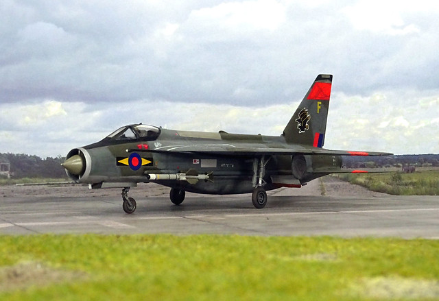
I was uncertain about the livery for a long time – I just had already settled upon an RAF aircraft. But the model would not receive a late low-viz scheme (the Levin, my mono-engine Lightning build already had one), and no NMF, either. I was torn between an RAF Germany all-green over NMF undersides livery, but eventually went for a pretty standard RAF livery in Dark Sea Grey/Dark Green over NMF undersides, with toned-down post-war roundels.
A factor that spoke in favor of this route was a complete set of markings for an RAF 11 Squadron Lightning F.6 in such a guise on an Xtradecal set, which also featured dayglo orange makings on fin, wings and stabilizers – quite unusual, and a nice contrast detail on the otherwise very conservative livery. All stencils were taken from the OOB Revell sheet for the Lightning. Just the tactical code “F” on the tail was procured elsewhere, it comes from a Matchbox BAC Lightning’s sheet.
After basic painting the model received the usual black ink washing, some post-panel-shading and also a light treatment with graphite to create soot strains around the jet exhausts and the gun ports, and to emphasize the raised panel lines on the Hasegawa parts.
Finally, the model was sealed with matt acrylic varnish and final bits and pieces like the landing gear and the Red Tops (taken OOB) were mounted.
A major effort, and I have seriously depleted my putty stocks for this build! However, the result looks less spectacular than it actually is: changing a Lightning from its literally original stacked engine layout into a more conservative side-by-side arrangement turned out to be possible, even though the outcome is not really pretty. But it works and is feasible!